Assembly process of rivet quick lock puller
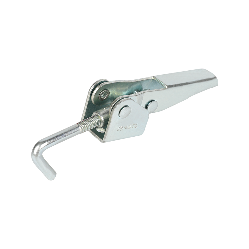
The assembly of Rivet Quick Latch Buckle Puller Latch Toggle Clamp is the process of combining various parts into a complete tool in an orderly manner according to specific design requirements. This process requires strict compliance with assembly specifications to ensure accurate coordination and collaborative work between various parts.
At the beginning of assembly, all parts need to be carefully cleaned and inspected. Cleaning is to remove impurities such as oil, iron filings, etc. attached to the surface of parts during manufacturing and transportation to prevent these impurities from affecting the operation of the tool after assembly and even causing wear of parts. Inspection focuses on the dimensional accuracy, surface quality and presence of defects such as cracks of parts. Only parts that have passed the inspection can enter the subsequent assembly link.
The assembly of the main structure is the core of the puller assembly. As the foundation of the puller, the main frame must have accurate installation holes and dimensional accuracy of each component. Place the pre-processed high-strength alloy steel main frame on a special assembly platform, and install the internal transmission components in sequence based on the frame. As a key component for the puller to achieve tension transmission, the drive screw has extremely high installation requirements. Carefully insert the screw into the corresponding mounting hole on the main frame, ensure the coaxiality of the screw through high-precision positioning tooling, and then tighten the screw with a special nut. During the tightening process, it is necessary to use a torque wrench to operate according to the specified torque value to ensure that the tightening force of each nut is consistent to avoid deformation of the screw or poor transmission due to uneven force.
The installation of the pulling head should also not be ignored. The pulling head is in direct contact with the rivet, and its installation accuracy directly affects the effect of the pulling operation. First, the pulling head is preliminarily docked with the end of the drive screw, and the angle and position of the pulling head are adjusted to make its center line coincide with the center line of the screw. Then use high-strength bolts to firmly connect the pulling head and the screw. During the connection process, the installation status of the pulling head should be checked several times to ensure that it will not loosen or deviate in subsequent use.
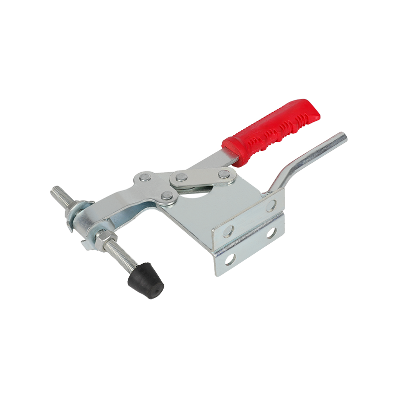
In addition to the main components, the auxiliary devices of the puller, such as operating handles, control mechanisms, etc., also need to be accurately assembled. The installation of the operating handle must not only ensure that its position conforms to the ergonomic design and is convenient for the operator to hold, but also ensure that the handle is tightly connected to the internal transmission components and can smoothly transmit force to the puller during operation. The assembly of the control mechanism needs to ensure the accurate linkage between the components, such as the connection between the tension adjustment knob and the internal transmission system. It is necessary to ensure that when the knob is turned, the tension can accurately change according to the set value.
Debugging process of rivet quick lock puller
The assembled rivet quick lock puller must also undergo strict debugging to ensure that its performance reaches the best state. Debugging mainly revolves around tension testing, transmission system testing, and operational performance evaluation.
Tensile testing is the key link in debugging. Fix the puller on a professional test platform, connect the tension sensor, simulate the actual working conditions of pulling rivets, and apply different tensions to the puller. The tension value generated by the puller is monitored in real time through the sensor and compared with the design standard. If the tension value does not meet the requirements, the transmission system needs to be checked and adjusted. This may involve readjusting the preload of the screw nut, or checking the clearance between the transmission components to ensure that the puller can generate stable and standard tension under various working conditions.
The transmission system test is to ensure that the internal transmission components of the puller run smoothly. Start the puller, observe the rotation of the transmission screw, and check whether there are abnormal phenomena such as jamming and abnormal noise. Use professional testing instruments to measure the speed and torque changes of the screw and analyze the efficiency of the transmission system. If the transmission is not smooth, it may be necessary to clean and lubricate the screw, or check whether key components such as bearings are worn and replace or repair them in time.
The operational performance evaluation starts from the perspective of actual use and verifies the convenience and comfort of the puller. Arrange different operators to use the puller to perform simulated pulling operations and collect feedback from the operators. Check whether the grip of the operating handle is comfortable and whether the operation of the control mechanism is flexible and accurate. According to the feedback from the operator, the shape, size or sensitivity of the operating handle or the control mechanism are appropriately adjusted to improve the overall operational performance of the puller.
Assembly process of locking toggle clamps
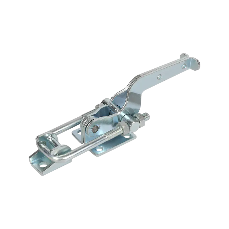
The assembly of locking toggle clamps is also a delicate work, and its assembly quality is directly related to the clamping force, self-locking performance and service life of the toggle clamps.
Before assembly, all parts must also be cleaned and quality inspected. The base, handle, connecting rod, lock and other parts must ensure that the surface is flawless and the size meets the design requirements. For some key parts, such as connecting rods and locks, strength and toughness sampling is also required to ensure that they will not be easily damaged during use.
During assembly, the base is used as the basis for construction. Place the base steadily on the assembly station and install the handle first. The connection method between the handle and the base is usually riveted or bolted. If riveting is used, special riveting equipment must be used to ensure that the rivets are firmly riveted and will not cause damage to the surface of the parts. The installed handle should be able to rotate flexibly, and the gap between it and the base should be uniform to ensure smooth operation.
The installation of the connecting rod is the key to achieving the clamping and loosening of the toggle clamp. According to the design requirements, the connecting rod is connected to the base, handle and lock in turn. During the connection process, the angle and length between the connecting rods must be accurately controlled to ensure the accurate motion trajectory of the four-bar linkage. Each connection point must be fixed with high-precision rivets or bolts. After fixing, the activity of the connecting rod must be checked to ensure that there is no interference or jamming during movement.
The installation of the lock directly affects the self-locking performance of the toggle clamp. The lock is accurately installed in the predetermined position, and the matching clearance between the lock and the connecting rod is adjusted to ensure that the lock can reliably achieve self-locking in the clamped state, and can be easily unlocked when it needs to be released. After the installation is completed, the lock should be opened and closed several times to check its elastic recovery force and locking accuracy.
Debugging process of lock toggle clamp
After the lock toggle clamp is assembled, debugging is essential to ensure its normal use and stable performance. Debugging mainly includes clamping force test, self-locking performance test and operation flexibility evaluation.
Clamping force test is an important indicator to measure the performance of the toggle clamp. Use a professional force measuring instrument to clamp the toggle clamp on the standard test block, gradually increase the external force, simulate the load conditions in actual use, and measure the maximum clamping force that the toggle clamp can provide. Compare the measurement results with the design requirements. If the clamping force is insufficient, it is necessary to check whether the installation angle of the connecting rod is correct or whether the preload force of the lock is appropriate, and make corresponding adjustments. Through repeated testing and adjustment, ensure that the clamping force of the toggle clamp meets the actual use requirements.
Self-locking performance testing is the key to ensuring the safety and reliability of the toggle clamp. After completing the clamping force test, keep the toggle clamp in a clamped state and apply a certain external force to it to simulate the impact or vibration that may be received during use. Observe whether the lock can remain locked and whether the workpiece will loosen. If self-locking fails, it is necessary to carefully check the structure and installation of the lock, adjust the fit between the lock and the connecting rod, and ensure that the toggle clamp can achieve reliable self-locking under various working conditions.
Operational flexibility evaluation focuses on the convenience of the toggle clamp in actual operation. The operator repeatedly tightens and loosens the toggle clamp to feel the resistance of the operating handle and the smoothness of the operation. Check whether the toggle clamp is flexible and easy to operate at different angles and positions. According to the feedback from the operator, the lubrication of the connecting rod and the tightness of the handle connection are adjusted to make the operation of the toggle clamp easier and more efficient.
The assembly and debugging process of the rivet quick lock puller and the lock toggle clamp ensures that these two tools can play a stable and reliable role in industrial production through strict control of every link, from the fine assembly of parts to the comprehensive debugging of the finished product. Every precise assembly and every round of strict debugging is to enable the tool to show excellent performance in actual use and provide a solid guarantee for the efficient operation of industrial production.
Industry News
Home / News / Industry News / How to ensure reliable performance during assembly and debugging of Rivet Quick Latch Buckle Puller Latch Toggle Clamp?
Industry News
Jun 19, 2025 POST BY ADMIN
How to ensure reliable performance during assembly and debugging of Rivet Quick Latch Buckle Puller Latch Toggle Clamp?
Message Feedback
News & EVENT
Product Categories
Recent Posts
If You Are Interested
In Our Products,
Please Consult Us
In Our Products,
Please Consult Us
Copyright © 2023 Shanghai Bingshuo Hardware & Machinery Co., Ltd. All Rights Reserved.
OEM/ODM Industrial Stainless Steel Hardware Latch Toggle Clamp Suppliers
Privacy
 English
 Español
 русский


